Although during construction of the wing we are mostly following Sandlin’s drawings and do not make any major alterations, we still want to make sure we are on the safe side. Especially considering that we haven’t seen any reports of wing load testing or structural calculations. Therefore we have carried out a numerical analysis of the wing structure based on a simplified CAD geometry still keeping the necessary complexity level including the pivot joints of main and jury struts and wing tube connections.
Here we are interested mainly in maximum equivalent stress on wing spar and main strut tubes. Additionally we want to make sure that main strut tubes are resistant against buckling under negative g loading.
The inputs are:
Maximum takeoff weight: 165 kg
Ultimate load factors: Positive: +6 g (+4*1.5); Negative -3 g (-2*1.5)
Assumed load distribution: 75% on the front spar (distributed evenly); 25% on the rear spar (distributed evenly)
Ultimate loads (per half-wing): Positive: 3675 N on front spar; 1225 N on rear spar; Negative: -1838 N on front spar; -613 N on rear spar.
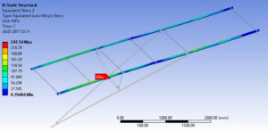
The results show that maximum stress (242 MPa) is located on the bottom side of the front spar between the internal struts #2 and #3. Maximum stress on the main strut (190 MPa) occurs on the main strut forward tube. These values are within material strength limits – for Al 6061-T6 various sources give yield stress between 240 and 270 MPa.
Concerning buckling resistance for the main strut tubes, Euler column formula gives following maximum permissible compression stress values:
Front tube: 121 MPa (max observed 96 MPa);
Rear tube: 91 MPa (max observed 75 MPa).
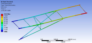
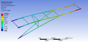
Wing element deformation analysis shows maximum deformation in the wingtip area. The front spar bending is larger, which is probably due to rather diverse loading distribution between the spars. 75%/25% is a rough approximation due to lack of aerodynamic data at the moment.
Some illustrations of the results are shown below:
Distribution of stress magnitude and location of maximum stress on spar tubes:
Wing element deformation under +6 g loading:
Wing element deformation under -3 g loading:


